Gán loại hố ga
Các hố ga sau khi phát sinh được lấy theo kiểu ga măc định. Lệnh gán kiểu hố ga có tác dụng đổi kiểu hố ga cho các hỗ ga đã có trên bản ve.
For every construction investment project, the total investment value is always one of the most crucial pieces of information. The total investment is comprised of multiple components, including land clearance compensation, construction costs, equipment expenses, financial costs, and more.
The costs that make up the majority of the total investment (land clearance and construction costs) are calculated based on a comprehensive quantity take-off. Even a small discrepancy in the quantity take-off can result in significant deviations in the total investment value (especially when required to multiply by various coefficients and percentages according to legal regulations).
Therefore, quantity take-off plays a crucial role and is an essential requirement for any infrastructure or civil construction project. This is why the methodology used for quantity calculation and the comprehensive quantity take-off table are always scrutinized carefully during the design review process, particularly for transportation and technical infrastructure projects, where the cut-and-fill volumes are extremely large.
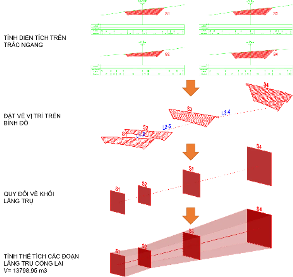
Traditionally, the quantity take-off for road alignment excavation and embankment is done using approximate conversion methods, where excavation and embankment volumes are simplified into basic geometric shapes to facilitate volume calculations:

In this method, the excavation and embankment volumes are approximated as prismatic volumes, where the area of the two bases is equal to the cross-sectional area, and the height is the difference in the chainage.
With the rapid development of Building Information Modeling (BIM) in the construction industry, the application of BIM in quantity take-off and project management is becoming increasingly common. Modern BIM software enables the automatic extraction of quantities for components and structures from the 3D model quickly and easily. Thanks to the ability to instantly update information when changes are made to the model, BIM has contributed to significantly improving accuracy in cost estimation.
To ensure legal compliance, Decision 258/QĐ-TTg on the "Approval of the roadmap for the application of Building Information Modeling (BIM) in construction activities" stipulates that "The key drawings and quantities of structural components must be extracted from the BIM file" (as stated in Article 1, Clause 2, Section c).
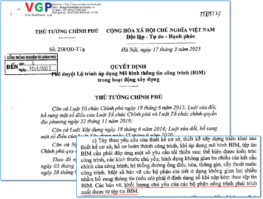
Decision 258/QĐ-TTg
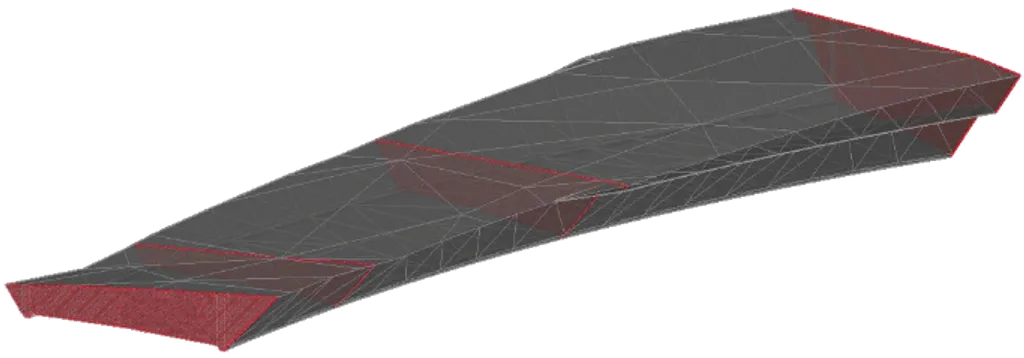
Cut-and-Fill Volumes in BIM Models
ADSCivil supports three methods for constructing volumes:
3D cut volumes: including slope cuts, road surface cuts, shoulder cuts, mud excavation, etc., where the upper surface is the existing terrain and the lower surface is the designed surface of slopes, road surfaces, etc.
3D fill volumes: including slope fills, road surface fills, etc., where the upper surface is the designed surface of slopes, road surfaces, etc., and the lower surface is the natural terrain.
3D volumes between geological layers: where the upper and lower surfaces are the boundaries of different geological layers.
Fill volumes excluding certain components such as road subgrade, longitudinal drains, retaining walls, etc. (e.g., slope fill volumes, combining fill volumes up to the finished slope surface minus 3D slope reinforcement, road surface fill volumes minus 3D road subgrade).
Excavation volumes divided by geological layers (e.g., embankment according to rock geology is generated from two volumes: the 3D embankment volume and the 3D rock geological volume).
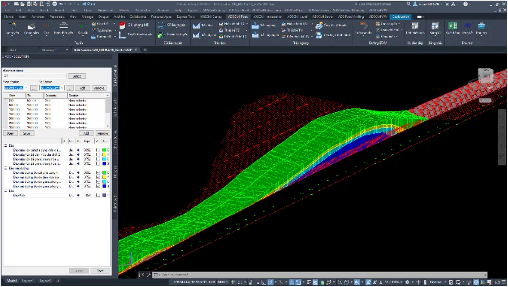
Illustration: Excavating Roadbed Based on Geological Layers (Composite Block - Type 3)
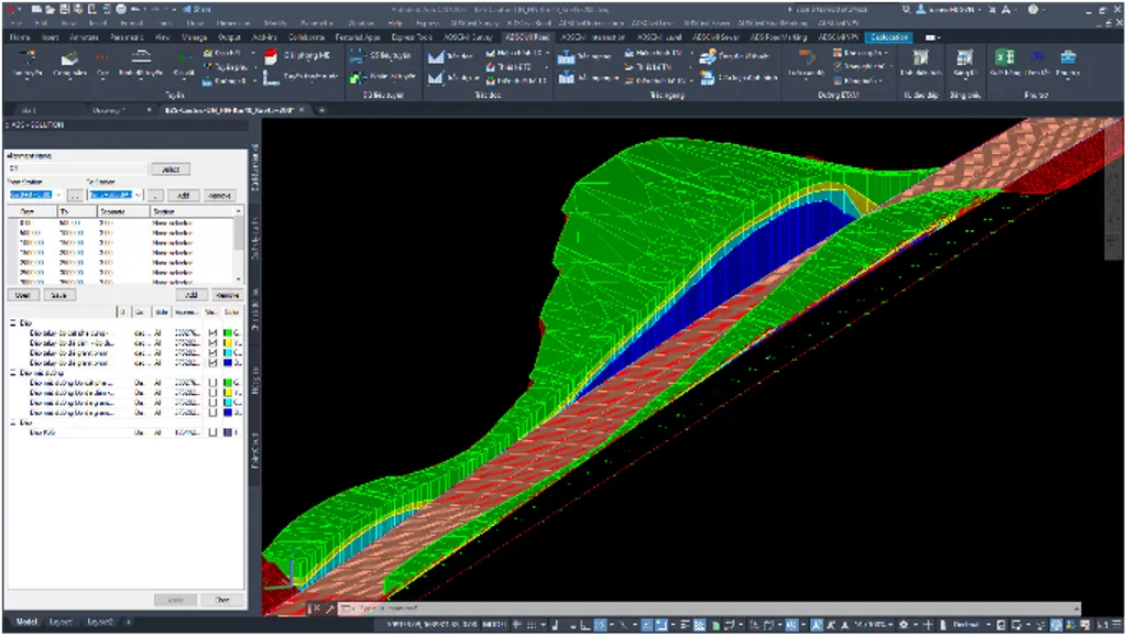
Illustration: Excavating Road Slopes Based on Geological Layers (Composite Block - Type 3)
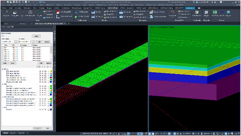
Illustration: 3D Block of Pavement Structure Layers (Type 1 Block)
Compared to traditional methods, the BIM model created in ADSCivil offers several outstanding advantages:
Issues can be easily observed and addressed during BIM meetings, where stakeholders review and make decisions based on the same visual model.
Unlike other applications that only generate design surfaces, ADSCivil precisely creates detailed shapes of soil and rock volumes, allowing for accurate volume extraction from the model. From these basic volumes, users can easily create composite volumes. After adjustments, ADSCivil still recognizes the model and automatically extracts quantities from it.
With precise intersections between the existing terrain and the design surface, land clearance boundaries and the project’s footprint are clearly defined. This allows social welfare issues to be addressed from the project's inception.
Accurate quantities contribute to more precise construction scheduling. Contractors can easily determine the quantities for each section and, based on their equipment capacity, develop appropriate timelines and methods.
The BIM cut-and-fill model for road alignments is highly intuitive, created quickly and with absolute accuracy based on survey data. This leads to more accurate design evaluations and makes comparing different design options easier. This assists designers in making precise decisions.
BAEZENISOFT CO., LTD
Address: 2nd Floor - CT1AB Building, Me Tri Plaza, Nam Tu Liem Dist, Hanoi
Hotline: 024.3200.5386 - 0987 779 228
Web: https://adscivil.vn/ or https://adscivil.com/